With the rapid advancement of science and technology, pump sealing has evolved from traditional packing/gland sealing methods to the current mechanical seal technology. Mechanical seals offer significant advantages, including reliable operation, minimal leakage, extended service life, and broad applicability, especially in industrial production. The fluids handled by pumps during operation are often corrosive, toxic, flammable, or explosive. Failure of a mechanical seal leading to media leakage not only causes environmental pollution but can also result in serious safety incidents and hazardous situations.
This study takes the DBM90A mechanical seal as an example. It thoroughly analyzes the optimal operating conditions for this seal type. Furthermore, it investigates common failure modes encountered in actual production settings. Based on this analysis, corresponding optimization measures are formulated to enhance the seal's performance and operational lifespan.
1 Structural Characteristics of the DBM90A Bellows Mechanical Seal
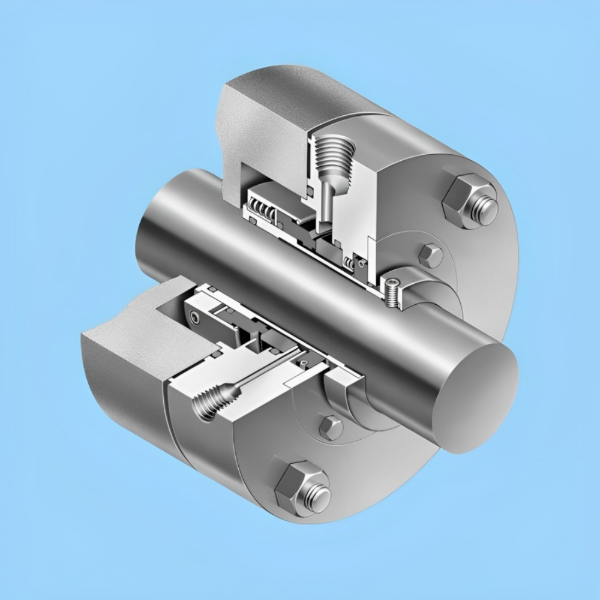
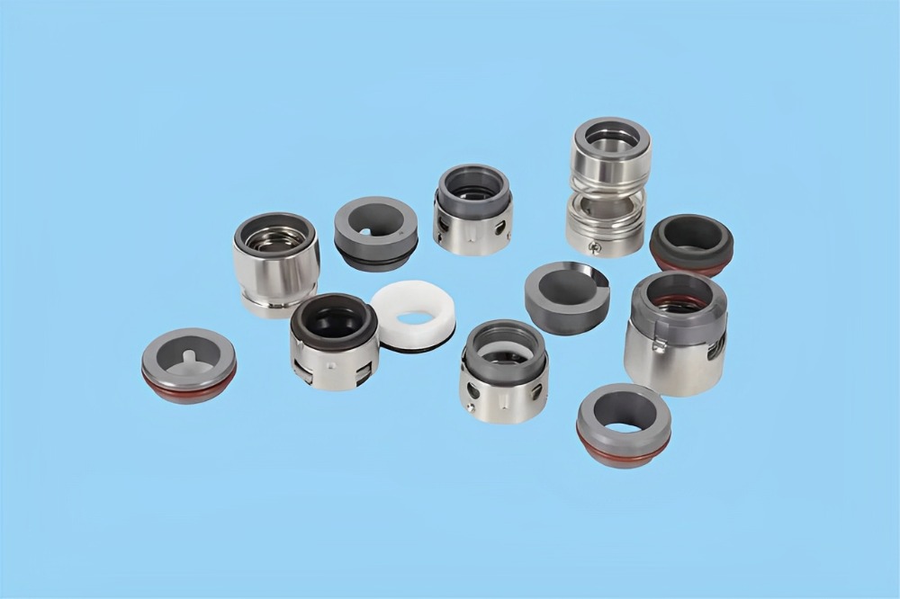
The structure of the DBM90A bellows mechanical seal is shown in Figure 1, with its geometric parameters detailed in Table 1. This assembly primarily consists of the following components: Rotating Ring, Stationary Ring, Seal Gland, Drive Ring, Drive Screws, Shaft Seal, Stop Collar, Stationary Ring Seal, Sleeve, Rotating Ring Seal, Hex Bolts, Positioning Ring, Throttle Bushing/Restriction Bushing, Buffer Fluid Ring, Socket Head Cap Screws.
This seal type is classified as an internally mounted seal, capable of withstanding elevated temperatures and pressures and exhibiting enhanced compensation capabilities. A key design feature is the integrated bellows and rotating ring, which rotates with the shaft during operation. The seal is rated for speeds up to 5000 r/min and an operating temperature range of -40°C to 260°C. The rotating ring is constructed from antimony-impregnated graphite, while the stationary ring utilizes silicon carbide. Both materials offer superior wear resistance.
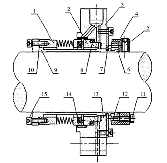
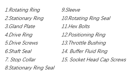
*Figure 1 Structure of the DBM90A Bellows Mechanical Seal
Seal Face Inner Diameter (mm) | 97 |
Seal Face Outer Diameter (mm) | 105 |
Bellows Inner Diameter (mm) | 92 |
Bellows Outer Diameter (mm) | 108 |
Bellows Thickness (mm) | 0.6 |
Number of Bellows Convolutions | 11 |
*Table 1 Geometric Parameters of the DBM90A Type Bellows Mechanical Seal
2 Failure Phenomena of the High-Temperature Oil Pump Mechanical Seal
Following the commissioning of a Residue Fluid Catalytic Cracking (RFCC) unit at a refinery, the high-temperature feed pumps (operating with one pump on standby) within the reactor effluent circuit experienced relatively frequent mechanical seal leakage. This leakage issue significantly impacted the unit's normal operation. The high-temperature feed pump model is 250YRSⅡ150×2. This pump is a two-stage, double-suction, between-bearings pump. Its key operating parameters are listed in Table 2.
Fluid Handled | Feedstock Oil |
| Inlet Pressure (MPa) | 0.75 |
Inlet Temperature (°C) | 234 | Outlet Pressure (MPa) | 2.69 |
Rated Flowrate (m3/h) | 473 | NPSHr (Net Positive Suction Head Required) (m) | 4.4 |
Designed Head (m) | 300 | Operating Speed (r/min) | 2950 |
**Table 2 Performance Parameters of the Feed Pump
During the period from April to May 2023, this pump experienced a total of seven mechanical seal failures. The primary failure modes were: coke deposition and blackening on the seal faces, and radial cracks originating below the seal faces, accompanied by white spots on the surface (Figure 2). Analysis of Failure Mode 1-Figure 2(a) reveals pitting on the outer radial surface of the seal bellows, specifically aligned with the flush fluid inlet port. Given the flush fluid port diameter is 16 mm and the flush fluid pressure is 0.9 MPa, the bellows damage is primarily attributed to long-term erosion caused by the impinging flush fluid stream. Analysis of Failure Mode 2-Figure 2(b) shows severe coke deposition on the seal faces. This occurs when high-temperature, high-density process media leaks and subsequently cokes (carbonizes) upon exposure to air or lower temperatures on the seal face surfaces.
a. pitting on the outer radial surface of the seal bellows b. severe coke deposition on the seal faces
*Figure 2 mechanical seal failures
Long-term on-site observations revealed that during operation, the pump exhibited noticeable cavitation noise. Multiple mechanical seal failures consistently manifested as catastrophic separation occurring instantaneously. Upon disassembly, significant amounts of irregularly distributed white spots (indicative of micro-fractures or heat checks) were observed on the seal faces, particularly on the stationary ring. In some instances, coke deposition on the seal faces was also present. Analysis of on-site temperature monitoring data for the pump's mechanical seal showed that the temperature of the flushing fluid, after being cooled via heat exchange, was 160°C. During pump operation, the mechanical seal temperature exceeded 180°C due to frictional heat generation at the seal faces and rotational heating effects generated by the rotating ring and bellows assembly. This temperature differential (from 160°C flush to >180°C seal face temperature) indicates inadequate heat removal. Consequently, the seal operated persistently at elevated temperatures, leading directly to thermal degradation and subsequent failure.
2.1 Seal Face Film Phase Analysis
Disassembly and inspection of the mechanical seal faces revealed:
a. Significant wear on the rotating ring face.
b. Numerous white spots and comet-tail patterns on the stationary ring face.
These observations indicate vaporization failure occurring at specific operating temperatures within the seal. The fluid film phase between the seal faces can undergo vaporization failure whether operating in a liquid-like or vapor-like phase state, leading to mechanical seal malfunction. The criteria for determining the phase state are detailed in Table 3. Analysis integrating the relationship between the feed pump's film pressure coefficient (Km) and the face temperature (TF) demonstrates that stable seal operation requires maintaining a load coefficient (K) greater than or equal to Km (K ≥ Km). This ensures optimal face conformity and stable film conditions.
Given the poor self-lubricating properties and high vaporization tendency of the pumped media, precise temperature control within the seal chamber is critical. This control is necessary to maintain the fluid film phase at the seal faces either fully in the vapor phase or fully in the liquid phase, avoiding the unstable mixed-phase region prone to vaporization failure.
Phase State | Determination Criteria |
Fully Liquid Phase Seal | tE<tba |
Fully Vapor Phase Seal | tE≥tba, tI>tb |
Liquid-like Phase Seal | tE≥tba, tF<tb |
Vapor-like Phase Seal | tE≥tba, tF>tb |
* Table 3 Phase State Criteria for Mechanical Seals
*Note:
tE: Temperature at the Seal Face Outlet (°C)
tI: Temperature at the Seal Face Inlet (°C)
tF: Temperature at the Seal Face Interface (°C)
tba: Atmospheric Boiling Point (°C)
tb: Boiling Point at System Pressure (°C)
2.2 Vibration Condition Analysis
This study analyzed the vibration characteristics of the pump during operation. The time-domain waveform of vibration at the pump coupling end is shown in Figure 3. Figure 3 indicates that the maximum vibration amplitude at the coupling end during operation was 0.41 mm. During pump operation, if shaft vibration reaches 0.4 mm, the resulting vibration amplitude difference at the mechanical seal rotating ring will reach 1 mm. This leads to a sudden increase in seal leakage. Furthermore, the seal bellows is subjected to high-velocity impingement from the flush fluid in the perpendicular radial direction during vibration. This further amplifies the perpendicular radial vibration amplitude of the rotating ring, placing the mechanical seal in an unstable operating condition and ultimately causing leakage failure. Additionally, the axial stiffness of the metal bellows is significantly lower than its circumferential stiffness. This stiffness disparity causes the metal bellows to undergo tilting vibration during pump operation. Consequently, the compensating ring (rotating assembly) impacts the non-compensating ring (stationary ring). Crucially, the DBM90A seal design lacks damping and vibration reduction features typically provided by auxiliary seal rings (O-rings/gaskets). The absence of damping allows the bellows to experience resonant excitation under external forces. This excitation leads to bellows fatigue cracking and ultimately results in mechanical seal failure.
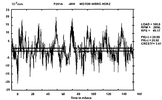
* Figure 3 Vibration Time-Domain Waveform at Pump Coupling End
2.3 Analysis of Pump Structural Factors
The design of the balance throttle section on the rear cover of the high-temperature feed pump described herein exhibits certain inherent design deficiencies:
a. Inadequate Throttling Rib Length: The throttling ribs within the rear balance chamber are significantly undersized. This prevents effective flow restriction of the media entering the second-stage impeller eye. Consequently, media bypasses the intended flow path.
b. Undersized Balance Line: Concurrently, the balance line diameter is insufficiently small. This, combined with the ineffective throttling, causes media to bypass into the seal chamber before it can adequately recirculate back to the pump suction. This results in elevated pressure and temperature within the seal chamber, ultimately leading to mechanical seal failure.
c. Balance Line Deformation and Restriction: Furthermore, the undersized balance line was observed to have bending deformation. This combination reduces the effective flow area and severely impedes media recirculation.
d. Insufficient cooling capacity: Finally, inadequate cooling water flowrate and insufficient heat exchanger surface area result in excessively high temperatures of the flushing fluid supplied to the seal. This critically hampers temperature control of the mechanical seal, causing seal overheating and subsequent failure.
3 Improvement Measures for the Pump Mechanical Seal
3.1 Balance Chamber Structural Modifications
This study implemented modifications to the pump's balance chamber structure:
a. Throttle Sleeve Redesign:
The throttle sleeve was remanufactured using 2Cr13 steel.
The sleeve length was increased from 115 mm to 146 mm.
The mating diameter clearance between the sleeve and the throttle bushing was controlled at 0.6 mm.
b. Balance Line Upgrade:
The balnace line diameter was increased from 12.70mm to 19.05 mm, this upgrade significantly increases the flow area of the balance line.
c. Balance Line Pressure Monitoring:
A pressure gauge was installed on the balance line, this enables real-time monitoring of balance line pressure. Pressure readings provide improved insight into the throttling effectiveness within the pump.
These modifications enhance throttling control at the second-stage impeller eye and increase the balance line flow area. Consequently, they effectively reduce pressure within the mechanical seal chamber. Crucially, this prevents uncooled media from entering the seal chamber, thereby avoiding the elevated temperatures that previously caused seal failures.
3.2 Modification of Shaft End Seal Flushing Scheme
The mechanical seal on this pump was primarily cooled using demineralized water (DM water), which proved ineffective during actual operation. Therefore, based on practical considerations, the improvement plan implemented a dual cooling approach combining an externally supplied barrier oil system with a barrier gas (nitrogen) quench system.
The specific operating parameters are set as follows:
Barrier Gas (Nitrogen) Quench:
Pressure: 0.7 MPa
Externally Supplied Barrier Oil System:
Oil Type: Vacuum Gas Oil (VGO) from the second side-cut distillate (Wax Oil)
System Pressure: 0.6 MPa
System Temperature: 75 °C
Seal Chamber Conditions:
Static Pressure: 0.17 MPa
Barrier Oil Injection Point:
Pressure: 0.25 MPa
Temperature: 70 °C
3.3 Modification of the Seal Flush Distribution Ring
This study involved the redesign and remanufacture of the seal flush distribution ring. The key modifications are:
a. Redesigned Flush Ports:
Six flush ports, each with a diameter of ϕ8 mm, were incorporated. The port locations were repositioned to be directly aligned with the rotating seal ring, which prevents the flush fluid from directly impinging on the bellows; The ports are oriented perpendicularly towards the top of the seal assembly. This orientation ensures uniform distribution of the flush fluid across the seal faces, significantly improving circumferential cooling.
b. Helical Throttle Groove:
A helical throttle groove, 20 mm in length, was machined into the head section of the distribution ring. This groove stabilizes the flow velocity of the flush media and prevents excessive flow velocity that could cause damaging impact on the bellows. Additionally, the helical groove promotes turbulent flow within the cooling fluid. Turbulence increases the residence time of the coolant in contact with the mechanical seal. This prolongs the heat exchange duration between the seal components and the coolant. Consequently, the overall cooling effectiveness of the mechanical seal is enhanced.
4 Conclusion
This study analyzed the structural characteristics of the DBM90A bellows mechanical seal, and involved a detailed investigation into the root causes of mechanical seal failures observed in a specific pump during operation. The analysis conclusively demonstrates that the primary factor leading to seal failure was vaporization of the media within the seal environment. Consequently, the core objective of the implemented seal modifications was thermal management – specifically, reducing the operating temperature of the mechanical seal.
The key modifications included:
Balance chamber structural redesign
Overhaul of the shaft end seal flushing scheme
Redesign of the flush distribution ring
Enhancements to the cooling water system
These comprehensive measures effectively lower the temperature during mechanical seal operation. As a result, the seal achieves significantly improved operational stability and an extended service life.
 한국어
한국어 ไทย
ไทย Español
 Português
 العربية
 Deutsch
 Pусский


