The assembly of mechanical seals constitutes the final stage in the machinery manufacturing process. It involves procedures such as the installation of sealing elements, clearance adjustment, leak testing, and adhesion verification. The assembly process establishes specific spatial relationships among seals, connectors, and locating components, thus necessitating thorough process design for mechanical seal assembly.
During the assembly process, all components must undergo measurement, cleaning, joining, alignment, adjustment, and final assembly. The dimensional inspection of each component of the bellows must be strictly verified against the designed theoretical tolerances. However, the unique operational characteristics of metal bellows necessitate not only specialized manufacturing processes but also specific assembly methodologies to achieve optimal performance and maximize efficiency.
1. Pre-Assembly Preparation
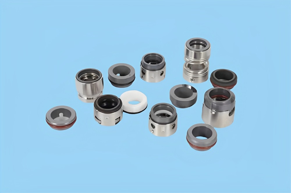
Proper installation of seals is critical to ensuring stable mechanical operation and extending service life. Therefore, seal installation demands particular attention. Prior to assembly, a thorough inspection must be conducted to verify that all required sealing components are available and that each part is intact and undamaged. Check the rotating and stationary rings for defects such as scratches, pits, cracks, or deformation. If any issues are identified, the affected components should be promptly repaired or replaced with intact ones.
2 Installation Technical Requirements
The overhaul of mechanical seals: as high-precision mechanical components, the accuracy of the mechanical seals demands that no impurities remain inside the seal. Before assembly, all parts—including the rotating and stationary rings, shaft sleeve, sealing rings, cooling devices, and compression springs—must be thoroughly cleaned to ensure they are spotless and free of contaminants. Special soft cloths shall be used to wipe the seal components, tools, lubricants, and the sealing faces of the rotating and stationary rings. All edges, chamfers, fillets, shaft sleeves, and seal cover flanges must be polished and deburred. During installation, lubricating oil should be applied to the rotating and stationary rings, auxiliary sealing rings, and end covers to reduce frictional resistance and prevent damage to the sealing surfaces and auxiliary seals.
Installation of auxiliary sealing Rings: Mechanical seals commonly use auxiliary sealing rings such as O-rings, X-rings, U-rings, and wedge-shaped rings. Since rubber-based materials are susceptible to corrosion, sealing rings must not be cleaned or soaked in gasoline, kerosene, or similar oils to avoid swelling and deformation, which would reduce service life. When installing O-rings onto stationary or rotating ring assemblies, ensure that any flash (molding line) is positioned on the transverse section of the ring in its free state. This prevents twisting or distortion by aligning the stress direction properly. Failure of rubber rings is often related to improper use, with high temperature and pressure being primary causes of failure in molded O-rings. If an O-ring deforms into a rectangular shape or hardens, adjust the compression level promptly; otherwise, overheating may occur. Therefore, it is essential to understand the operating temperature range of each type of synthetic rubber. During component operation, prevent O-ring leakage caused by wear. Common forms of seal damage include chipping, cracking, impact marks, rolling, twisting, plastic deformation, and aging.
Adjustment according to technical requirements: Different assembly requirements dictate specific compression levels for sealing elements. During installation, the compression of the mechanical seal must be adjusted in accordance with technical specifications—reference values can typically be found in relevant standards. Insufficient compression may lead to inadequate specific pressure between the rotating ring and the sealing surface, resulting in poor sealing performance. Conversely, excessive compression increases surface pressure, accelerates wear at the interface, and likewise impairs sealing effectiveness.
3. Assembly of Cartridge Mechanical Seals
3.1 Installation of Sealing Ring into the Non-Compensating Ring
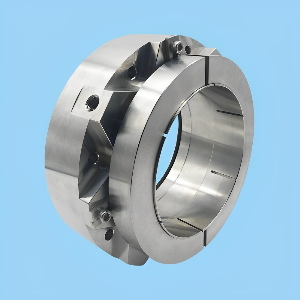
Tighten the set screw into the tension ring, ensuring that the screw does not protrude beyond the inner diameter of the ring. Assemble the non-compensating ring and the tension ring into a integrated component using spring washers and connecting screws. Throughout this process, care must be taken to protect the sealing faces of the friction pair. After installing the rotating ring, verify that it can rotate freely and smoothly. The spring mechanism must return automatically to its original position after being compressed. Dedicated tools must be used for any tapping or pressing operations during installation to prevent damage to seal components, as illustrated in Figure 1.
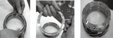
Figure1 non-compensating ring and tension ring were assembled into a integrated component
3.2 Installation of Sealing Ring into the Gland and Placement of Metal Bellows Assembly
The process of installing the sealing ring into the gland is relatively complex. First, mount the stationary ring sealing ring onto the back of the stationary ring, and then insert the entire assembly into the seal end cover. Inspect the metal surfaces in contact with the shaft sleeve and gland to ensure they are free from noticeable damage, scratches, or nicks. Verify that the end face of the stationary ring is perpendicular to its central axis within specified tolerances. Align the anti-rotation slot on the back of the stationary ring with the anti-rotation pin, as illustrated in Figure 2.
Invert the seal and connect the metal bellows assembly to the gland using spring washers and connecting screws. Tighten the screws evenly and diagonally to the specified torque in a crisscross pattern to ensure uniform load distribution. During this operation, care must be taken to protect the friction pair surfaces; a rotary mechanical seal refers to a type of seal in which the compensating ring is assembled with the shaft and rotates synchronously with it.
Handle sealing components with care during installation to prevent impact or abrasion that could compromise sealing integrity. Prior to assembly, clean and dry all seals and housing cavities using designated cleaning fluid. When tightening the gland, apply force symmetrically and uniformly to the fastening bolts, following a cross pattern sequence to avoid stress concentration or mechanical seal failure. For quick-assembly mechanical seals, radially move the positioning clip away from the shaft after completing the assembly. Note that sealing media and chamber pressures vary across mechanical seal types. As a result, assembly and maintenance procedures may differ accordingly, as shown in Figure 3.
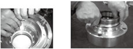
Figure 2 metal bellows assembly Figure 3 metal bellows assembly were
were positined into the gland connected with the gland
3.3 Installing the Gland Sealing Ring and Metal Bellows Assembly
Install the gland sealing ring into the gland groove, and then sleeve the metal bellows assembly onto the shaft sleeve. The mechanical seal, after being cleaned, organized, inspected, and verified, can be reassembled. During this process, special attention must be paid to the following points:
●All sealing rings should be adequately lubricated prior to assembly to avoid damage caused by hard friction between components.
● During the assembly of the floating ring, do not touch the floating ring spring, as this may affect its floating performance.
● After assembling the floating ring, perform a simple test by gently actuating it to observe whether it moves freely and returns smoothly.
When disassembling mechanical seals, tools with excessive hardness such as hammers or chisels must not be used to prevent damage to seal components. If mechanical seals are installed at both ends of a component, exercise extreme caution during disassembly to avoid simultaneous removal, which may lead to misalignment or uncontrolled release. For seals that have completed the run-in period, if the sealing surface shifts when the gland is loosened, it indicates failure of the rotating or stationary ring, and these components must be replaced immediately. Once the gland is loosened, the operating trajectory of the friction pair is altered, compromising the surface finish of the sealing faces and resulting in irreversible wear that cannot be remedied through adjustment.
If seal components are bonded by dirt or solidified deposits, remove the residue prior to disassembly, as shown in Figure 4.
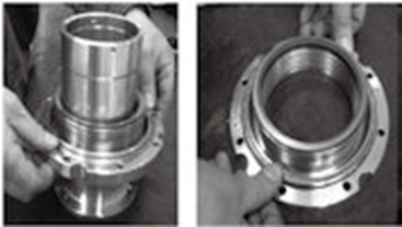
Figure 4 metal bellows asembly were sleeved onto the shaft sleeve
Mechanical seals are generally categorized as internally mounted or externally mounted seals. Externally mounted mechanical seals refer to those installed outside the sealed cavity.
Internally mounted mechanical seals are generally preferred for most applications due to their superior force environment, where the specific pressure increases with rising medium pressure. In this configuration, the direction of leakage is opposite to that of centrifugal force during operation, enhancing sealing reliability. However, externally mounted mechanical seals are typically employed when the fluid lubricating medium is highly corrosive.
Installation Note:
Clean the friction pair surfaces, install the non-compensating ring assembly onto the shaft sleeve, and bring the sealing faces into contact gradually to avoid impact.
4. Quality Inspection
Assembled products shall be transferred to the next process using dedicated transport equipment, where professional inspectors from the company's quality department will perform quality checks.
4.1 Handling Common Leakage Issues in Mechanical Seals
Leakage during operation is a frequently encountered issue in mechanical seals, often resulting from various factors. A common cause is fluid leakage due to deformation of the contact surfaces between the rotating and stationary rings.
Excessive specific pressure on the sealing faces can lead to overheating from friction, which may cause bending deformation of the rings. In such cases, immediately inspect the sealing faces for thermal deformation. If thermal deformation is found, replace the rings promptly. If no deformation is detected, the leakage may stem from insufficient assembly accuracy. In this situation, reassemble the seal following standard procedures.
4.2 Analysis of Common Operational Failures in Mechanical Seals
In addition to leakage, improper material selection of auxiliary sealing elements can cause swelling and loss of elasticity, requiring replacement with compatible seals. Excessive deviation in perpendicularity between the sealing faces of the rotating/stationary rings and the shaft sleeve axis may also lead to accelerated wear. In such cases, check whether shaft runout exceeds allowable limits; if so, repair or replace the shaft promptly. If the rotating/stationary rings and associated sleeve components cannot compensate for wear in a timely manner, clean any accumulated contaminants without delay.
Experimental research has shown that improved assembly accuracy of metal bellows seals significantly enhances their operational reliability. Higher precision not only extends the service life of the seal but also ensures the efficiency and performance of related mechanical components.
Practice has proven that optimal assembly quality is fundamental to maximizing the service life of metal bellows seals. This directly contributes to greater enterprise profitability and represents a critical factor in advancing industrial development toward more modern and efficient manufacturing standards.
 한국어
한국어 ไทย
ไทย Español
 Português
 العربية
 Deutsch
 Pусский


